
WP valves in chloromethane compressors: a 16,000-hour average life
At a chemical plant in Jiangsu, China, valves in four low-pressure chloromethane compressors lasted from a few days to about two months. RONDER selected WP-type valves for the gas and operating conditions, carried out dynamic calculations, and designed and checked the engineering drawings. After the change, the valves achieved an average service life of 16,000 hours. This case describes the likely failure mechanisms and the transient valve-motion analysis behind the redesign.
In petrochemical and fine-chemical plants, reciprocating compressor valves commonly account for more than 60% of unplanned compressor shutdown failures. Chloromethane (CH3Cl) is moderately toxic and flammable, with an explosion hazard. Frequent valve failures in this service raise spare-parts costs and affect mean time between failures (MTBF), hot-work safety and losses from unplanned reduction in plant throughput.
When valves last days, or a month or two, instead of several thousand hours, replacing like for like does not solve the problem.
Case background and operating problem
A chemical plant in Jiangsu, China, operated four multi-throw, low-pressure reciprocating chloromethane compressors in a critical production unit. The design discharge pressure was approximately 1.0 MPa. Suction and discharge valves began failing soon after commissioning:
- Short valve life: from a few days to about two months.
- Frequent unplanned shutdowns: each unit was switched over and isolated for maintenance more than ten times a year on average.
- Maintenance burden: work on valves in flammable, toxic chloromethane service required depressurisation, nitrogen purging, blind isolation and leak-tightness testing. Each intervention was time-consuming and carried safety risks.
- Repeated failure after like-for-like replacement: the original-specification metal ring valves were replaced several times, yet valve elements continued to break and springs suffered fatigue failure.
The customer asked RONDER’s valve engineering team to investigate the root cause and redesign the assemblies for the operating requirements.
Failure analysis: likely causes
The gas carried small amounts of liquid, was relatively dirty and ran under varying conditions. We considered three likely mechanisms.
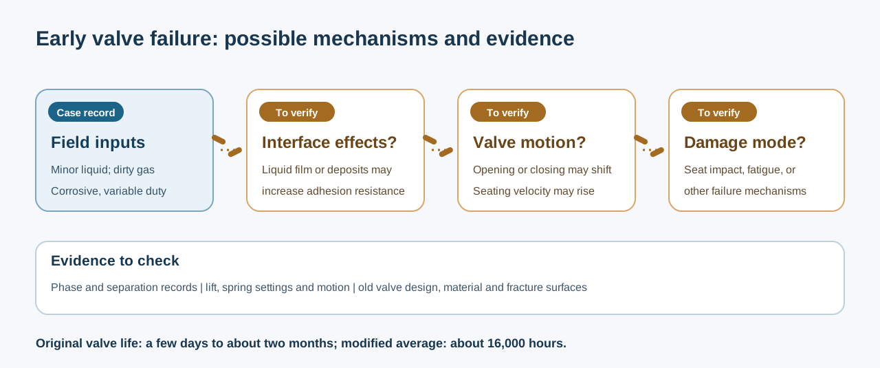 Diagram: possible mechanisms and evidence to check
1. Liquid carryover and liquid-film adhesion (liquid stiction)
Pure chloromethane boils at about −24.2°C at atmospheric pressure. At 1.0 MPa absolute, its saturation temperature is about 46°C; a gas mixture’s dew point depends on composition and pressure. Cooling or operating fluctuations near the dew point can cause condensation and liquid carryover. A liquid film between the seat and valve element can resist opening and delay valve motion. Local liquid accumulation can impose impact loads that increase fracture risk.
2. Delayed closing and seat impact
Nominal gas velocity alone may miss the changing balance between aerodynamic force and spring restoring force. Dynamic calculations should check whether the valve element closes late and whether its seating velocity exceeds the design limit for the structure and material. Late closing can raise impact velocity; repeated impacts may lead to fatigue damage.
3. Limited tolerance of metal sealing faces to fine hard particles
Fine solids carried by the process gas can enter the sealing interface. Rigid impacts on a metal valve element can initiate small cracks at stress concentrations; repeated loading may cause them to grow through the part.
RONDER’s valve design and engineering checks
RONDER developed the modification around the gas service and operating conditions, with particular attention to potential closing delay and impact:
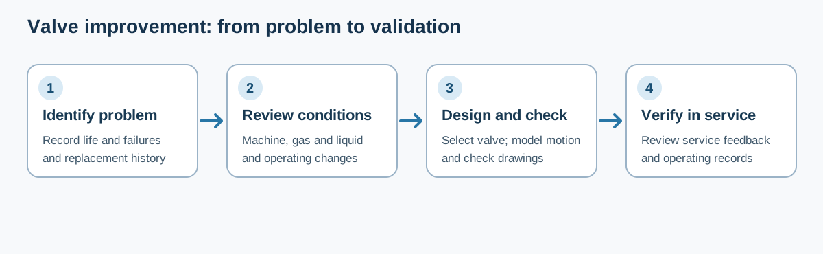 Diagram: engineering checks and validation of valve dynamics
1. Valve redesign: WP-type non-metallic damped mesh valve
The reciprocating compressor valve product page describes the WP type’s published design features.
- Moving element material: the team selected a specially modified PEEK with chemical resistance, self-lubricating properties and resistance to impact fatigue. Compared with conventional alloy-steel valve elements, the lighter PEEK elements reduced inertial impact energy by more than 60% under the same aerodynamic force.
- Liquid tolerance and damping: the elasticity and damping of PEEK help soften contact impact, while the geometry and surface condition of the sealing faces influence liquid-film adhesion. Material changes must be combined with upstream gas-liquid separation measures.
- Concentric flow passages: the valve-seat flow profile was revised to reduce local recirculation and pressure drop (ΔP), while controlling gas temperature rise.
2. One-dimensional transient valve-motion analysis
Valve motion depends on the changing balance of spring force, aerodynamic force and inertia during the compression cycle. For these machines, RONDER’s engineers modelled transient valve motion using actual operating speed and suction and discharge thermodynamic conditions:
- Valve lift: lift was selected by balancing effective flow area, suction and discharge pressure drop, and closing kinetic energy.
- Spring loading: spring stiffness and preload were recalculated against gas density, pressure history and aerodynamic forces at operating speed, then matched with moving mass and lift. The analysis checked closing phase, rebound and seating velocity to reduce flutter and impact. The closing phase for each suction and discharge valve was determined from its respective pressure-difference history.
The lift plots, spring stiffness values and tolerances are covered by a confidentiality agreement. For each compressor we prepare a Valve Motion Dynamic Simulation Report covering the design inputs, calculated valve motion and check results.
Design comparison and operating results
The customised WP-type valve assemblies were installed on all four machines during a major overhaul, following design review, precision manufacture and coordinate measuring machine (CMM) inspection of geometric tolerances.
Technical comparison
| Assessment | Original metal ring valve | RONDER customised WP-type mesh valve |
|---|---|---|
| Moving element material | Alloy-metal elements had greater moving mass; repeated impacts led to fatigue cracks and breakage. | Lighter modified-PEEK elements use material elasticity and damping to soften contact impact. |
| Tolerance of small amounts of liquid | Liquid-film adhesion affected the metal contact faces, which offered limited impact cushioning; loads from local liquid accumulation increased breakage risk. | PEEK elements and sealing-face design control liquid-film adhesion, while elasticity and damping reduce impact loads. |
| Dynamic matching | The conventional spring configuration was poorly matched to aerodynamic forces and element inertia in this duty; delayed closing and higher seating velocity could result. | A transient dynamic model was used to match spring stiffness, preload and lift, control closing phase and seating velocity, and reduce seat impact. |
| Flow resistance and power loss | Flow passages and effective area were poorly matched, with greater local pressure drop and valve-related power loss. | Flow profile, effective area and lift were optimised together to reduce pressure drop (ΔP) and valve-related power loss. |
| Service life (original range / modified average) | A few days to two months, with repeated shutdowns following valve breakage. | Average service life of 16,000 hours. |
Results in service
- Longer service life: after the modification, average valve service life reached 16,000 hours during sustained full-load operation, reducing unplanned shutdowns caused by valve failures.
- Lower maintenance exposure: dozens of purge-and-isolation maintenance operations involving a toxic, flammable gas were avoided each year. This improved on-site control of health, safety and environmental (HSE) risks.
- Annual costs: each compressor saved several hundred thousand yuan a year in labour, spare parts and losses from reduced production.
What to send before an assessment
If valves are failing earlier than expected, discharge temperature is high, or valve elements break repeatedly, an OEM or plant equipment team should gather the following information before requesting a modification proposal:
- Machine and operating conditions
- Compressor type, cylinder bore, stroke, operating speed, and suction and discharge pressures and temperatures at each stage.
- Gas composition analysis, with particular attention to heavier hydrocarbons, corrosive components or possible liquid carryover.
- Existing valve history
- Valve type currently fitted: ring, mesh, poppet or straight-through.
- Failure history, including average running hours and the first component to fail: valve element, spring, seat sealing face or lift limiter.
- Clear photographs of failed components, including fracture surfaces, uneven wear and deposits or coking.
Request a compressor valve reliability assessment
Repeated valve breakage often points to a mismatch between valve dynamics and actual operating conditions. To discuss the factors limiting valve life on a specific reciprocating compressor, send the machine model, operating conditions and a short failure history to RONDER’s engineering team:
- Technical enquiry: sales@ronder-valve.com
- Scope: root cause analysis (RCA) of reciprocating compressor valve failures, dynamic checks of gas forces and valve motion, and customised valve design for longer service life and performance improvements.
Further reading
- Claudio Vaglini. Compressor Valves. EFRC Training Workshop, 2015. See Valve Dynamics, Valve Reliability and Failure Analysis.
- Klaus Brun and Marybeth Nored. Valve Performance and Life of Reciprocating Compressors. Texas A&M University, Turbomachinery Laboratories, 2012.
- American Petroleum Institute. API Std 618, Reciprocating Compressors for Petroleum, Chemical and Gas Industry Services, sixth edition. See the API standards catalogue for edition information. General standards reference.
- NIST Chemistry WebBook, SRD 69. Chloromethane — Antoine Equation Parameters. The temperature cited above is calculated for pure chloromethane.
- Electrical and Mechanical Methods for Detecting Liquid Slugging in Reciprocating Compressors. International Compressor Engineering Conference at Purdue, 2008.
Related product
Related technical cases
- Flare Gas Compressor Valve Upgrade | RONDER
- Compressor Valve Replacement: Monthly to Annual Maintenance | RONDER
View all technical resources and cases