
1800 r/min valve design for an international compressor OEM
RONDER developed valves for a compressor with a design speed of 1800 r/min and obtained acceptance of the revised design from the international OEM’s engineers. As of the date of this publication, valve localization was complete, while compressor production trials were still ongoing.
The internationally known manufacturer was localizing compressor production in China and wanted to source the valves locally as well. RONDER identified shortcomings in the existing valve design, substantiated the proposed changes with valve motion simulation results, and was selected as a valve supplier for the localization project. The model had the highest speed among the production models for which RONDER had supplied valve designs at the time documented in this case.
Valve timing at high speed
At 1800 r/min, the crankshaft turns 30 times per second, with each revolution taking approximately 33.3 milliseconds. The valves must operate within the corresponding suction or discharge portion of that cycle.
Ideally, a compressor valve opens when required and closes when required. Higher speed shortens the time available and leaves less margin for timing errors. With an unsuitable configuration, the valve plate flutters or closes late.
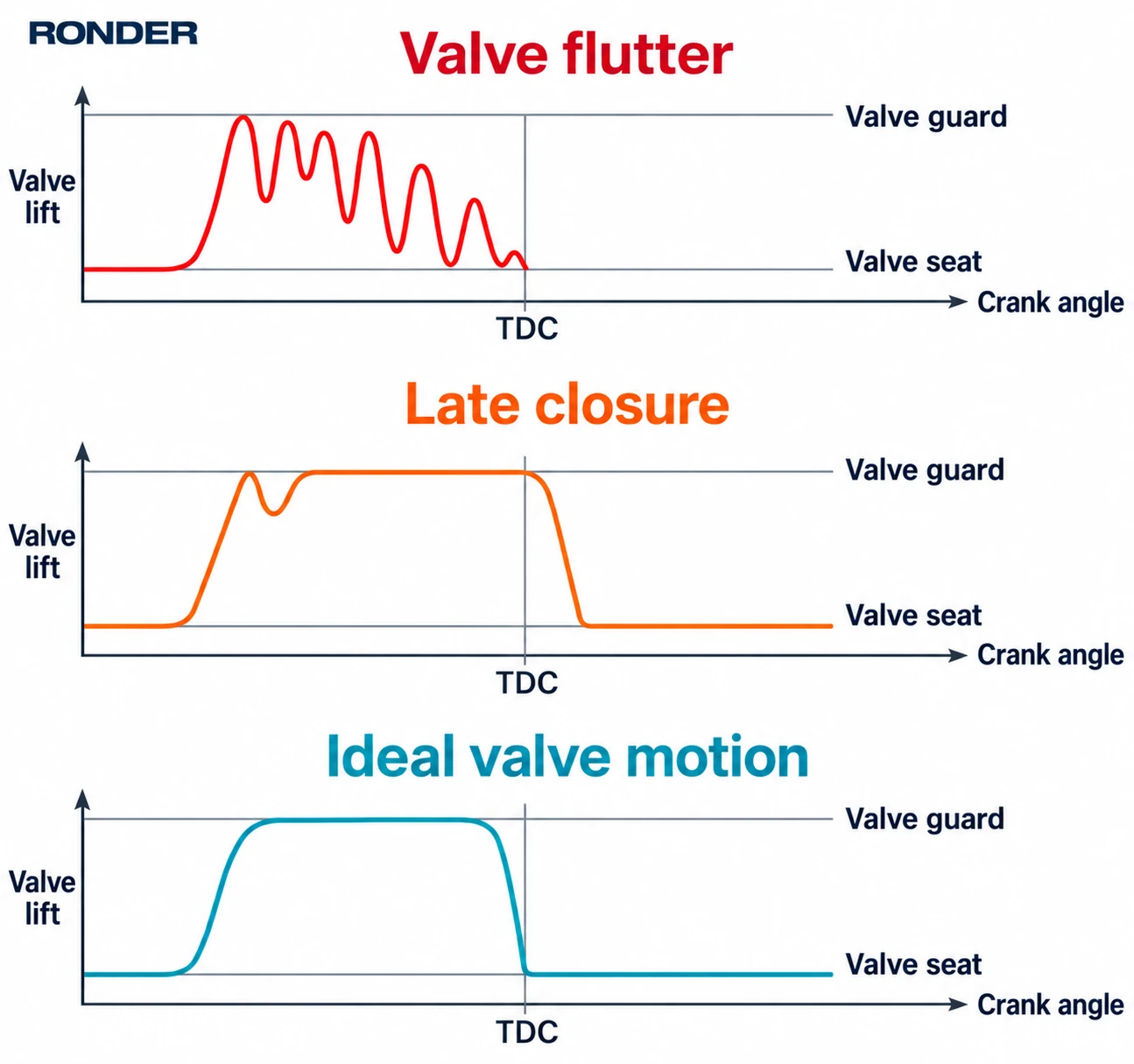
Figure 1. Schematic valve motion. From top to bottom: valve flutter, late closure and ideal valve motion. The curves show valve lift against crank angle.
A valve dynamic study can examine when the valve plate opens, whether its motion remains stable and whether it returns to the valve seat in time. Static calculations and experience-based selection cannot predict these dynamic behaviors; valve motion simulation is required.
Impact, flow and fatigue
Impact velocity during opening and closing
During opening, the valve plate contacts the valve guard or lift stop; during closing, it returns to the valve seat. Even with suitable timing, excessive impact velocity can damage the plate and contact surfaces. Plate mass, valve lift, spring characteristics and gas forces must be considered together, with a valve dynamic study used to assess velocity at contact.[1]
Valve lift and flow capacity
Reducing valve lift shortens the plate’s travel but also reduces the flow area available through the valve gap. For the same compressor model, stroke and suction conditions, increasing speed generally means handling more gas per unit of time. Insufficient flow capacity increases pressure loss, while greater lift can increase dynamic loads on the moving components. Lift selection therefore needs to account for the flow passages in the valve seat and guard, as well as the valve gap.[1]
Fatigue and wear under repeated loading
For a valve that completes one opening and closing cycle per crankshaft revolution, 1800 r/min corresponds to approximately 108,000 cycles per hour. At 8,000 operating hours per year, this amounts to approximately 864 million cycles. Valve plates and springs undergo repeated loading, and contact surfaces experience repeated impacts. RONDER accounts for cyclic stresses, impact conditions and operating temperature in material and structural design, and verifies durability through testing.[2]
Reviewing the design with the OEM
RONDER submitted the reasons for the changes together with the valve motion simulation results and discussed the revised design in depth with the manufacturer’s engineers. The review focused on valve plate motion, and the OEM accepted RONDER’s proposal.
Project status
Valve localization is complete. Localization of other components is progressing at different rates, and compressor production trials are ongoing.
Discuss your compressor valve requirements with RONDER
For compressor production localization or valve design for a high-speed model, email sales@ronder-valve.com with:
- Your company and contact details, compressor model, project stage and valve requirements;
- Design speed, operating speed range, compression stage and suction or discharge valve location;
- Gas composition, suction and discharge pressures and temperatures for each stage, flow rate and load range;
- Mounting interface details or existing valve drawings that you can share, and the issues the current design needs to address;
- Material, testing and acceptance requirements, and project milestones.
For valve types and construction features, see reciprocating compressor valves.
References
- European Forum for Reciprocating Compressors. Compressor valves. See the Layout section for flow area, valve lift and valve motion.
- Klaus Brun and Marybeth Nored. Valve Performance and Life of Reciprocating Compressors. Texas A&M University, Turbomachinery Laboratories, 2012.
Related product
View reciprocating compressor valve products
Related technical cases
- HK Hydrogen Valves: 8,000+ Hours Without Failure | RONDER
- WD Valves for a CO₂ Compressor: 8,000+ Hours Without Failure | RONDER
View all technical resources and cases